Why We Replaced Three Highlighter Geometry Engines with Stamps
 Gaoge Zhang
Real Apple Pencil data exposed defects that synthetic tests missed, leading Lulucat Notes from three outline engines to a MaLiang stamp model.
Lulucat Notes began with a conventional highlighter renderer: build a geometric outline around the sampled path, then fill that outline once with a translucent colour. A single fill avoids the darker bands that appear where translucent segments overlap. It also places every join, self-intersection, cap, and short stroke inside the same geometry problem.
Three generations of custom geometry each removed one class of defect and exposed another. The renderer we ship now uses soft circular stamps based on MaLiang, an MIT-licensed open-source drawing framework by Harley-xk. In exchange for removing a whole category of outline failures, we accepted darker self-intersections and pressure-tapered ends.
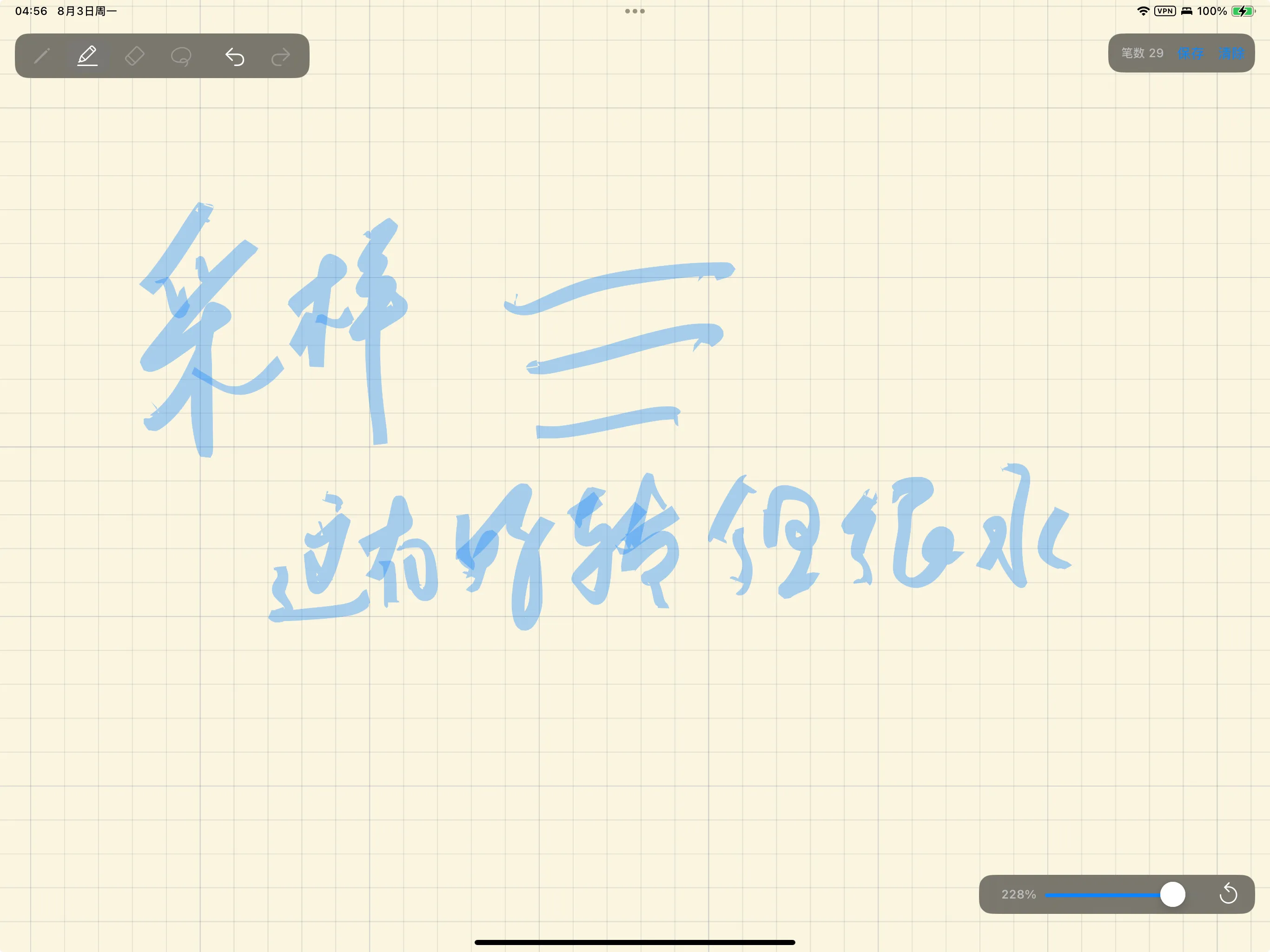
The original device screenshot at 228% zoom. Small hooks appear on both ends of several strokes.
Real handwriting produced hooks that synthetic scenes did not
Our synthetic scenes covered straight lines, arcs, short taps, backtracks, pressure changes, and sharp turns, and all of them rendered cleanly. Real Chinese handwriting still produced hooks about 1–3 points long at the beginning and the end of many strokes.
We therefore added a save button to the app and recorded 29 complete strokes. Every sample kept its position, radius, pressure, azimuth, altitude, timestamp, and UIKit estimation flags. An offline program decoded that JSON and compiled the same Stroke.swift, StrokeRenderer.swift, and HighlighterStrokeBuilder.swift files the app uses. Its output matched the device screenshot stroke for stroke, including the hooks.
Because the offline renderer reproduced the defect from recorded input alone, the cause lay in the samples and the geometry rather than in display behaviour. We could now read the exact samples that had entered the renderer.
Our first hypothesis blamed estimated Pencil orientation at touchdown and lift-off. The data rejected it. Across all 29 strokes, azimuth changed by at most 0.09 radians and altitude by at most 0.02 radians within the first and last eight samples, and every estimation flag was false on that iPad. Orientation stayed stable while pressure and direction changed sharply.
A pressure floor came from a clean gap in the data
The last sample of every recorded stroke had pressure 0.000. Writing samples sat at or above 0.01, while samples recorded after the Pencil had left the surface sat at or below 0.002. Those airborne samples often continued for 2–7 points and travelled 0.8–9.0 points, and their direction could turn by roughly 90 degrees away from the written stroke.
Stroke 2 shows the mechanism. Its body ended between 143 and 180 degrees. The low-pressure tail then turned to −90 through −67 degrees and travelled another 8.5 points. The outline renderer treated the final airborne point as the authoritative endpoint, so it stretched a narrow piece of geometry toward that point.
The measured pressures leave almost an order of magnitude between writing and airborne movement, so we put the cutoff inside that gap:
private static let pressureFloor: CGFloat = 0.005Only low-pressure samples at the two ends are removed. A low-pressure sample in the middle of a stroke remains part of it. The rule follows the measured event boundary and leaves the written path unedited.
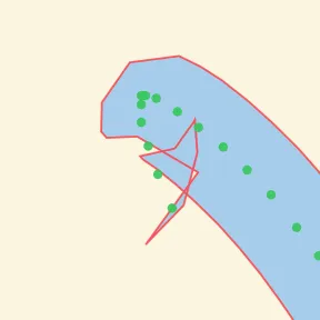
Before trimming, the renderer anchors the cap to airborne samples. Green dots are raw samples; the red line is the generated outline.
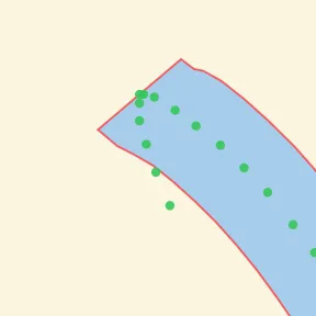
After trimming samples below 0.005, the cap ends at the last written point. This pressure floor remains in the current stamp renderer.
The floor removed the long airborne hooks. Short touchdown drags and lift-off arcs whose pressure stayed above 0.005 survived it, because they are written motion. Handling those motions inside an outline model led to the next rounds of geometry.
Three geometry engines moved the defects around
Generation one: one outline, one fill
The first pressure-sensitive engine followed a familiar pipeline. It smoothed a spine, calculated left and right offsets, joined them into one polygon, and filled that polygon once. The nib was an ellipse driven by Apple Pencil azimuth and altitude, so its cross-section changed with writing direction. Short taps had a separate shape, and flat caps used small asymmetries to avoid zero-winding pockets.
The single fill solved opacity accumulation inside a stroke, and it required a valid polygon at every turn. Touchdown drags created wedges between the cap and the body. Backtracks could create white crescent pockets. Sharp turns could make the inner outline self-intersect and leave an unfilled notch.
Generation two: repair the outline near its ends
The second engine kept the outline and added local repairs: backtrack trimming, damping for early estimated properties, endpoint straightening, transient-direction trimming, and a small cap extension. Each patch addressed a reproduced failure. Together they made endpoint behaviour depend on several thresholds and windows.
Real writing then produced cases outside those windows. A fixed 24-point straightening window erased intentional hooks in short strokes. An adaptive window preserved those hooks, and lift-off arcs could still become visible corners. Direction-aware trimming removed more transient motion, at the cost of discarding about 2.5 points of a genuinely curved start in one recorded stroke.
Each patch fixed its target case. The model underneath them still required a hard outline that stayed valid under noisy, curved input.
Generation three: coverage union with clipped square caps
The third engine stopped constructing a single contour. It drew a trapezoid for each segment and a disc at each interior sample into a greyscale mask, took their coverage union, then applied the highlighter colour once. Backtrack crescents, self-intersection darkening, and zero-winding holes disappeared, because the renderer no longer depended on polygon winding.
The union rounded the ends, and we restored square caps by clipping coverage against two endpoint half-planes. That clip fixed constant-pressure straight lines and introduced a more serious defect: the body of a curved stroke can legitimately cross an endpoint half-plane, and the cap clip then removed part of the middle of the stroke. During live input the endpoint direction kept changing, so the clipped area moved and the stroke flickered.
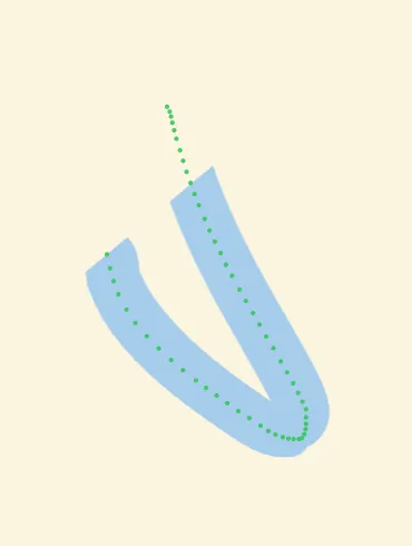
The global cap constraint cuts through the body of a curved stroke.

Restricting cap clipping to primitives within one half-width of the endpoint restores this stroke.
An arc-length gate made cap clipping local and repaired every recorded case. An extreme synthetic hook still showed a small white notch where a low-pressure tip met the clipped cap. The third engine had again traded one geometry failure for another.
MaLiang removes the hard boundary
MaLiang builds a stroke from repeated texture stamps rather than one closed outline. Its path generator uses quadratic Bézier segments that pass through adjacent sample midpoints, and its line renderer places stamps at a regular step along that path. Stamp size, rotation, colour, and opacity can all vary along the stroke.
A soft stamp carries no separate cap, join, or winding rule. A sharp change in direction stays a sequence of overlapping marks. Backtracks cannot create an empty polygon pocket, and an endpoint half-plane cannot cut the middle of a stroke, because the model contains no endpoint clip.
We adopted the model rather than the code. The current HighlighterStrokeBuilder performs four operations:
- Remove only endpoint samples whose pressure is below
0.005. - Smooth positions with midpoint quadratic Bézier segments.
- Place one circular stamp per point of arc length.
- Set stamp diameter from normalized pressure and composite the stamps with source-over alpha.
The builder fell from 686 lines to 190. Azimuth, altitude, outline construction, union masks, endpoint direction windows, cap extension, and cap clipping all left the highlighter path. We still record Pencil orientation, because the input model supports it, and the highlighter itself no longer reads those fields.
MaLiang’s pressure formula needed device calibration
MaLiang sizes a stamp with a formula equivalent to
which assumes that force uses a useful part of the range from 0 to 1. Our device data did not. Across about 3,400 Apple Pencil samples, median pressure was 0.047 and the maximum was 0.178. Feeding those values directly into the formula made normal writing much thinner than the nominal brush size.
We therefore normalize around the observed median, then apply the exponent and clamp the result:
The median written pressure now maps to the nominal 12-point diameter. Very light contact stays visible at 35% of nominal size, while heavy pressure stops growing at 120%.
This calibration belongs to the input device and to brush behaviour rather than to MaLiang. Copying the original formula without measuring our own pressure distribution would have preserved the architecture and produced the wrong brush.
Per-stamp alpha came from the known overlap count
MaLiang compensates for overlapping translucent stamps with the empirical expression alpha ÷ overlapping × 2.5. Our brush has a fixed 12-point nominal diameter and a 1-point stamp step, so its centreline receives about 12 layers. In our case the overlap count is known, and the compensation can be solved instead of estimated.
For a target stroke opacity
so one stamp requires
With
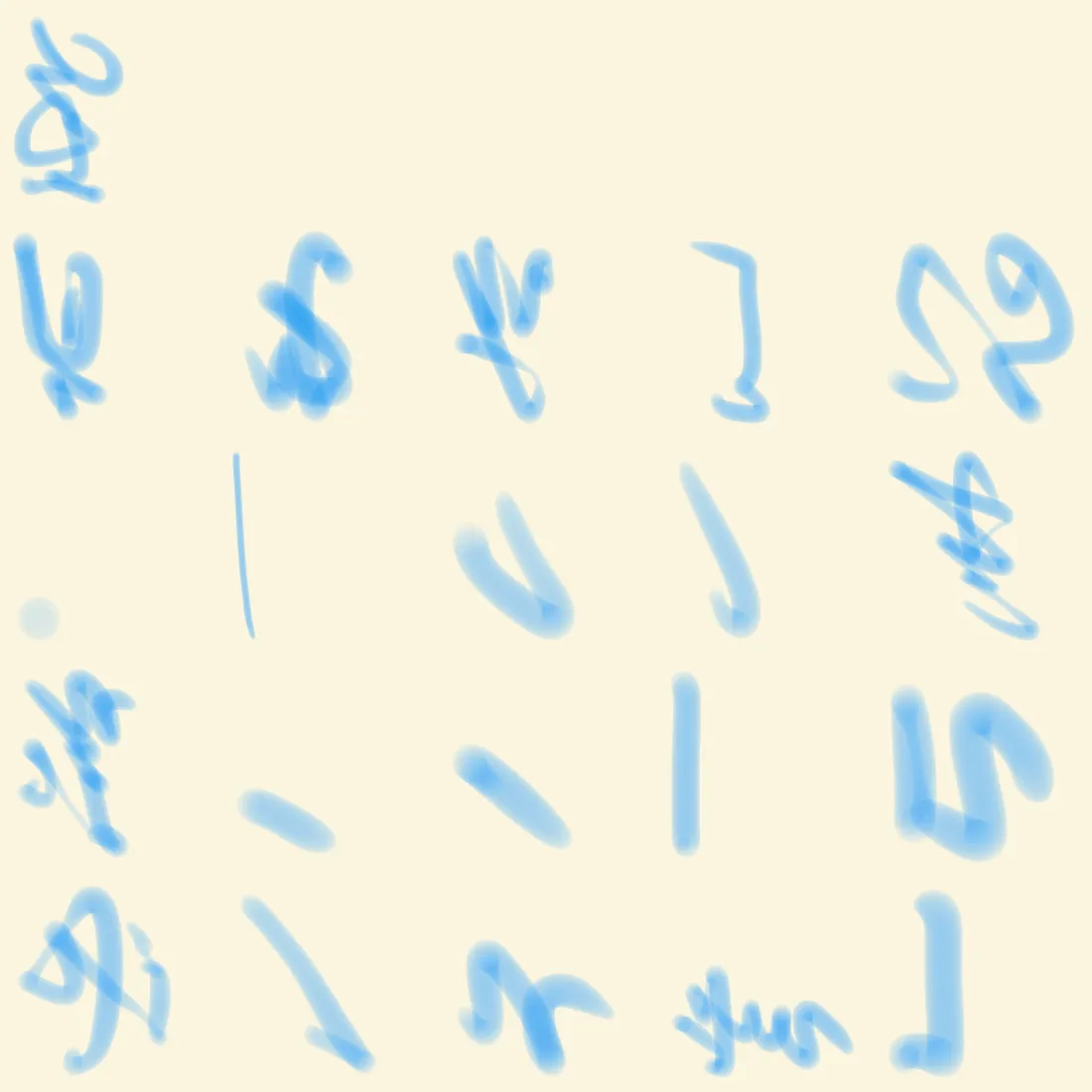
The final renderer replaying the recorded device paths. Hooks, diagonal cuts, and white pockets are absent.
The two costs we accepted
Self-intersections become darker. Source-over composition counts every stamp, including stamps laid down by an earlier pass through the same area, and the coverage-union engine had avoided that. We accepted the darker overlap because it is predictable and leaves the stroke shape intact.
Endpoints narrow with pressure. A real lift-off reduces pressure, which reduces stamp diameter, so the stroke tapers rather than ending in a full-width square cap. We had treated that square cap as a requirement through all three geometry engines. Dropping it removed the clipping and endpoint machinery behind several of the failures above, so we accepted the tapered end.
The model we ship therefore does less than the ones before it. It preserves the measured writing event, responds to pressure after device calibration, and renders curved and self-crossing paths without requiring a globally valid outline. A chisel-shaped nib, a perfectly square cap, and the exact polyline between raw samples are the features we gave up for that.
The pressure floor transfers most directly to other projects. The value 0.005 came from the gap between two clusters in real input: writing at 0.01 and above, airborne tracking at 0.002 and below. The same recorded strokes showed where each geometry repair failed. Those failures led to the stamp model and the two costs it carries.